

Endüstriyel otomasyon ve enstrümantasyon
alanında geniş bilgi birikimi, yetenek ve güçlü
deneyimle teknoloji hizmetleri sunmak.
Aktek olarak başarının ancak yüksek
teknolojili ürün, hızlı servis, tecrübeli ve
dinamik bir ekiple sağlanabileceğine inanırız.
Üretimde kaliteyi ve verimliliği artıran yüksek teknoloji enstrümanları sunan şirketimiz, sürekli yenilenen bilgisi, tecrübesi, titizliği ve en iyiyi elde etme azmi ile müşterilerine satış öncesinde optimum çözüm sunar.
2008 yılından sonra oluşturduğu AKTEK markası ile daha dinamik ve daha gelişimci bir imalat sürecine giren işletmemiz, sürekli yeni ürünler geliştirerek, size daha iyi hizmet etmek için çalışmaktadır.

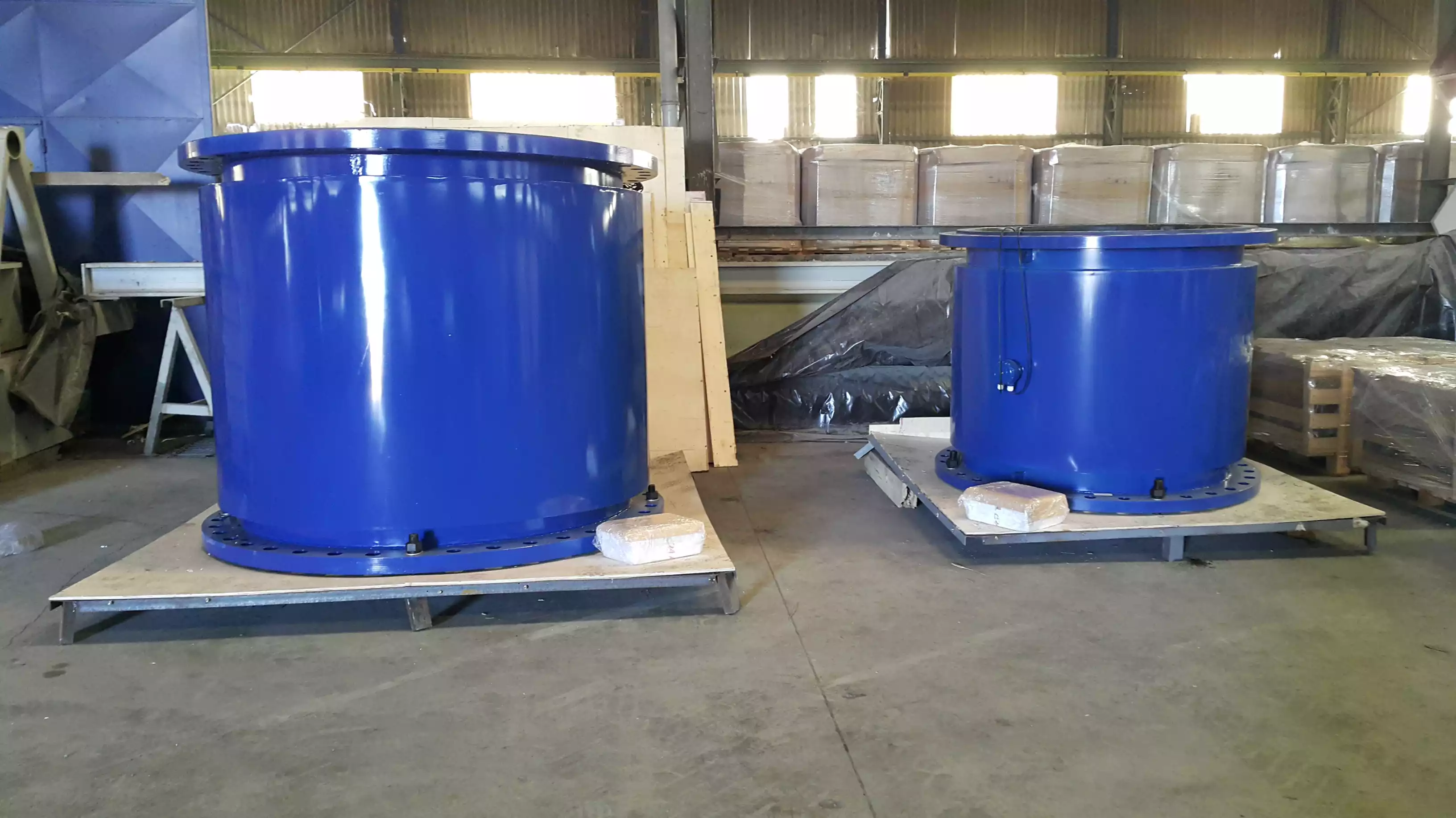
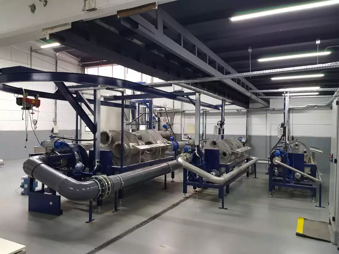
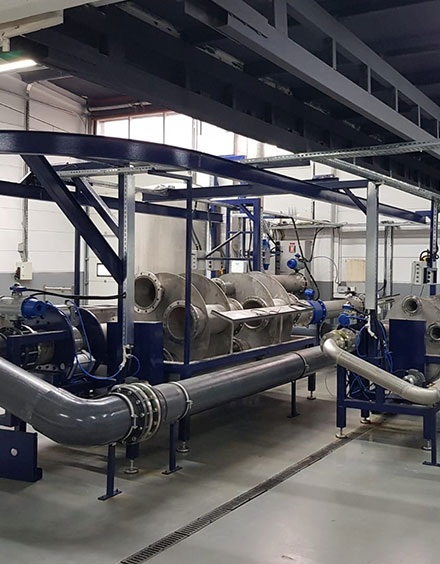
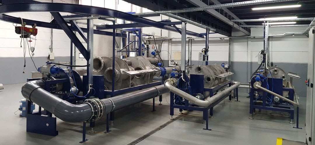
Elektromanyetik, Ultrasonik geçiş süresi, Doppler, Vortex ve Mekanik akış ölçerler gibi WINCC scada yazılımı ile desteklenen kalibrasyon tezgahımızda her türlü sıvı akış ölçerinizin kalibrasyonunu yapıyoruz.


yıldan fazla tecrübe
AKTEK markası altında, yüksek teknolojiyle donatılmış enstrümanlarımız ve sürekli yenilenen yaklaşımımızla, üretimde kaliteyi şekillendiriyoruz.
Dinamik ve gelişimci bir anlayışla sizlere en iyi hizmeti sunmaya devam ediyoruz.