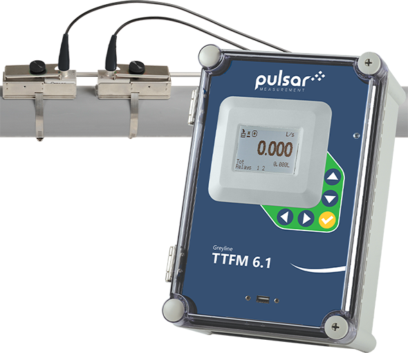


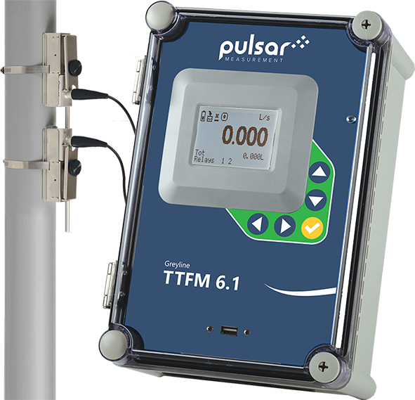
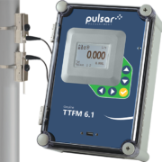
Transit Time Ultrasonic Flow Meter TTFM 6.1
• 1/2” through 48” pipe range
• Simple 5-key Configuration
• 4-20mA/0-5V Output
• 26 Million Point Data Logger
• Backlit LCD Display
• Password Protected
• Modbus® RTU or HART Optional
- Description
- Application Areas
- Specifications
- Brochure
- User’s Guide
- How It Works
Product Description
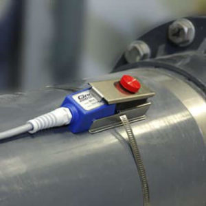
- Accurately measure the flow rate of relatively clean, non-aerated liquids like potable water, raw water, cooling water, de-ionized or reverse-osmosis water, oils and chemicals in full pipes. Ultrasonic transducers mount on the outside of a pipe without shutting down flow. Flow rate is displayed on the large, backlit display, along with total volume, signal strength, relay status, and other diagnostic values. Use the built-in control relays as flow alarms or volume totalization. Connect the isolated 4-20mA output to PLC’s or controllers. A 128MB data logger is standard, capable of capturing up to 26 million data points. Optional MODBUS RTU via RS-485 available for connection to automation systems.The TTFM 6.1 works on a wide range of pipe sizes and materials including carbon steel, stainless steel, ductile iron, concrete lined ductile iron, cast iron, PVC, PVDF, fiberglass, copper, brass, aluminum and pipes with bonded liners including epoxy, rubber and Teflon.The TTFM 6.1 Transit Time Flow Meter operates by measuring the “transit time” or “time of flight” for ultrasonic sound pulses transmitted from one transducer to another. Depending on the mounting configuration, the signal may cross the pipe once, twice or four times. To measure flow the transit time is compared between ultrasonic signals travelling upstream and downstream.TTFM 6.1 Standard Features Include:
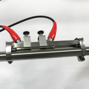
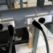
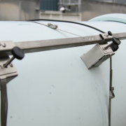
- One pair of SE16B ultrasonic transducers – clamp-on for 2” to 48” (50 mm to 1200 mm) pipes
- Optional: one pair of SE16A ultrasonic transducers – clamp-on 0.5″ to 4″ (13 mm to 100 mm) pipes
- Sensor cables – pair 25 ft / 7.6 m triaxial with BNC connectors
- Flow rate range: ± 0.07 to 40 ft/sec (± 0.02 to 12 m/sec)
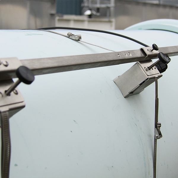
- Installation – stainless steel transducer mounting brackets and clamps, alignment bar and silicone coupling compound kit
- Enclosure – watertight, NEMA4X (IP66) polyester and polycarbonate
- Display – white, backlit matrix
- Totalizer – 14 digits
- Programming – built-in 5-button keypad
- Output – isolated 4-20mA (1000 ohm)
- 2 Control relays – 5 amp, SPDT – programmable for flow proportional pulse output, and/or flow alarm
- Power input – 100-240VAC 50/60Hz, 10VA maximum (Optional: 9-36VDC, 10 Watts maximum)
- Data Logger – 128MB storage capacity, 26 million data points, formattable as .csv or .lg2 for Greyline Logger Software
- Electrical surge protection and RFI filters – AC, sensor, 4-20mA
- Plug-and-play options including MODBUS RTU output and extra control relays
• Treated Water
• Raw Water
• Cooling Water
• Chemicals
• Hydraulic Oil
• Low-Conductivity Water
• Water / Glycol Solutions • Diesel & Fuel Oils
SCOPE: This specification covers a Clamp-On Transit Time Ultrasonic Flow Meter as manufactured by Greyline Instruments, Largo, Florida / Long Sault, Ontario. The meter shall provide for non-intrusive flow measurement, direction indication, volume totalizing, and transmitting of the flow rate in a full pipe.
A. PERFORMANCE SPECIFICATIONS
The ultrasonic flow meter shall have an accuracy of ±1% of reading or ±0.015 ft/sec (±0.0046 m/sec), whichever is greater. Have repeatability and linearity of ±0.25%.
Shall operate on relatively clean liquids in full pipes with less than 2% solids or gas bubbles at flow velocities from ±0.07 to 40 ft/sec (±0.02 to 12 m/sec).
Operate on any metal, or plastic, sonic conducting material including carbon steel, stainless steel, ductile iron, concrete lined ductile iron, cast iron, PVC, PVDF, fiberglass, galvanized steel, copper, brass and pipes with bonded liners including epoxy, rubber and Teflon.
The ultrasonic flow meter shall be optimized and pre-programmed for the application when information like pipe material, pipe size, wall thickness, fluid type, fluid temperature, and max flow rate are provided at time of order.
B. TRANSDUCERS (FLOW SENSORS)
The flow meter shall have a dual transmitting/receiving, clamp-on transducers.
The transducers shall operate continuously at temperatures from -40°F to 300°F (-40°C to 150°C).
The transducer pair shall be designed to install on pipes with inside diameter ranging from 2" to 48" (50 mm to 1200 mm).
Have 25 ft (7.6 m) length triaxial cables from the electronics with BNC connectors to transducers.
Shall include manufacturer's recommended sensor coupling compound. Shall include stainless steel mounting hardware with pipe clamps.
Shall include BNC seal jackets for transducer operation in wet or submerged conditions up to 10 psi (0.75 bar).
Transducers shall be rated non-incendive for Class I, Division 2, Groups A, B, C & D locations.
C. ELECTRONICS
The electronics shall be housed in a watertight and dust tight NEMA4X (IP 66) polyester and polycarbonate enclosure with a gasketed shatter proof window, and suitable for wall mounting.
Flow meter electronics shall be designed to operate at temperatures from -5°F to 140°F (-20°C to 60°C). The transmitter circuit and calibration frequency standard shall be crystal controlled. The transmitter shall be powered by 100-240VAC 50/60Hz requiring less than 10VA.
The transmitter shall include a built-in 5-Key calibration system with operator selection of parameters through visual prompts from a Menu calibration system. Systems requiring calibration by Parameter codes or external calibrators shall not be accepted.
The 4-20mA shall be flow proportional and isolated, with programmable zero and full-scale offsets. Maximum resistive load shall be 1000 ohms. It shall include automatic high voltage bleeds for nearby lightning strikes.
Electronics shall include noise suppression circuitry to filter electrical interference.
Electronics shall have a white, backlit matrix LCD display indicating flow rate in user-selected engineering units, units of calibration, relay states, signal strength, measured fluid speed of sound, and 14-digit totalizer.
Electronics shall have 2 control relays rated 5 amps SPDT. Relays shall be programmable for flow proportional pulse output, or as flow rate alarms with separate ON/OFF set points.
Electronics shall display and totalize forward and reverse flow.
Electronics shall have built-in data logger capable of storing up to 128MB of data. Data can be downloaded to flash drive via USB type-A port on the meter’s front panel.
Electronics shall be modular and field replaceable by means of plug-in circuit boards. The instrument shall detect and load software menus automatically for field-installed options.
D. OPTIONAL FEATURES FOR INSERTION IN SPECIFICATION AS REQUIRED:
The transducer pair shall allow for installation on pipes with inside diameter ranging from 0.5” to 4” (15 mm to 100 mm). Shall include BNC seal jackets.
The transducer pair shall allow for installation on pipes with inside diameter ranging from 0.5” to 4” (15 mm to 100 mm). The transducer cable shall be directly connected to the transducer, and potted to allow for installation in wet environments. IP67 protection rating.
Transducer cables shall be 50 ft (15m) length triaxial with BNC transducer connections.
Transducer cables shall be 100 ft (30m) length triaxial with BNC transducer connections.
Transducer cable shall be extended length shielded triaxial pair up to 500 ft (150 m) with NEMA4X (IP 66) Junction Box.
Electronics shall include a MODBUS® RTU output via RS-485 or HART. Data points for Modbus shall include flow rate, flow total, previous day’s average flow rate, previous day’s volume total, totalizer reset, relay output status, signal strength, measured fluid speed of sound, run time, transducer connection status, logger status, and percent log used. HART shall be version 7.0, with DD files compatible with Emerson 475 HART Field.
Transducers shall be rated Intrinsically Safe for Class I, Division 1, Groups C and D; Class II, Groups E, F and G; Class III; Type 4 hazardous locations.
Electronics shall have a thermostatically controlled AC-powered enclosure heater for condensation protection in locations with temperature below -5°F (-20°C).
Electronics shall have power input of 9-32VDC requiring less than 10 Watts.
Electronics shall have 4 additional (6 total) control relays, rated 5 amps SPDT and programmable for flow rate alarms or flow totalizer pulse.
E. MANUFACTURER
The instrument shall be a Model TTFM 6.1 Clamp-On Transit Time Flow Meter as manufactured by Greyline Instruments, and warranted against defects in materials and workmanship for one year.
Specifications are subject to change without notice.
Please contact Greyline if you need more information or for advice in your application. We can provide quotations and refer you to the Greyline sales representative in your area.
Ultrasonic Flow Meter TTFM 6.1
USER'S GUIDE TTFM 6.1
Transit Time Flow
Transit Time flowmeters measure the time it takes for an ultrasonic signal transmitted from one transducer to cross a pipe and be received by a second transducer. Upstream and downstream time measurements are compared. With no flow, the transit time would be equal in both directions. With flow, sound will travel faster in the direction of flow and slower against the flow.
Very accurate timing circuits are required but 1% accuracy is quite typical when the transducers can be mounted on a pipe section with evenly distributed flow.
Because the ultrasonic signal must cross the pipe to a receiving transducer, the fluid must not contain a significant concentration of bubbles or solids (less than 2%). Otherwise the high frequency sound will be attenuated and too weak to traverse the pipe. Applications include potable water, cooling water, water/glycol solutions, hydraulic oil, fuel oils and chemicals.
Transit Time transducers typically operate in the 1-2 MHz frequencies. Higher frequency designs are normally used in smaller pipes and lower frequencies for large pipes up to several meters in diameter.
Related Products
-
 Request a QuoteQuick View
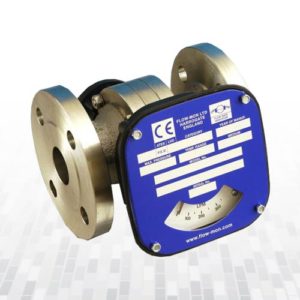
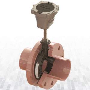
Mechanical Flow Meter Medium Serie
Switches: field adjustable, suitable for batching,
trending, totalising or recording where required.
0-10 v or 4-20mA output. -
 Request a QuoteQuick View
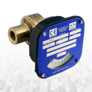
Mechanical Flow Meter Small Serie
-
 Request a QuoteQuick View
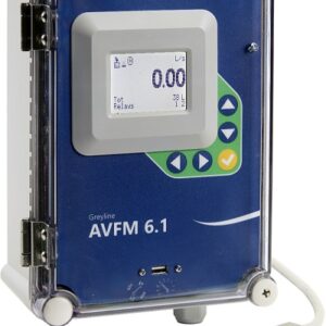
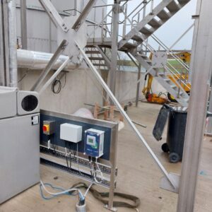
Area-Velocity Flow Monitor AVFM 6.1
- No flume or weir required – submersible ultrasonic sensor measures velocity and level simultaneously to calculate flow. No moving parts to wear, foul, or clog.
- Built-in 5-button keypad, intuitive menu, and large backlit LCD display make the AVFM 6.1 the most operator-friendly area velocity flow meter on the market.
- Fast, simple, installation and setup.
- Improved performance in a wider range of operating conditions.
- At a glance, view flow rate, velocity, level, totalizer, relay status, and important diagnostic information on the LCD display.
- Three isolated 4-20mA outputs for flow rate, velocity, and level, and two relay outputs for pulse output or alarm.
- 6.5 million point data logger for greater flexibility of data monitoring, control, and reporting.
- Min, Max, and Total Flow data from the last 365 days is available on the LCD display, or download directly to a USB for easy reporting.
- Monitors flow rate, volume total, run hours, and diagnostic information through only two wires with the optional Modbus RTU serial communication output.
-
 Request a QuoteQuick View
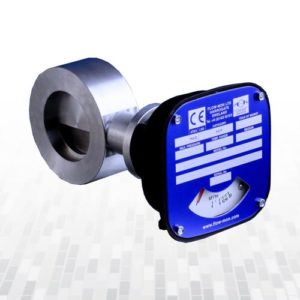
Sandwich Type Ultrasonic Water Meter TFMW-1
Sandwich Insertion Ultrasonic Water Meter is a new style water meter specially designed for agricultural irrigation, Garden Management and water resource supervision.
Advantages of this water meter ;
Low cost, high accuracy, low power consumption, stability and reliability.
1 inch thickness of the meter helps to save installation space, and parts to achieve IP 68, enable the water works in any severe environment .
Due to unique design, there will be no pressure loss and different water medium will have no influence on measurement
Analog, Digital outputs and RS485
-
 Request a QuoteQuick View
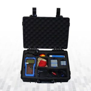
Portable Ultrasonic Transit Time Flow Meter TFM 1100P
- Backlit LCD Display
- Simple –16 key Calibration
- Built-in data-logger
- High accuracy measuring
- Wide measuring range from DN15 to DN6000
- RS-232 serial interface
-
 Request a QuoteQuick View
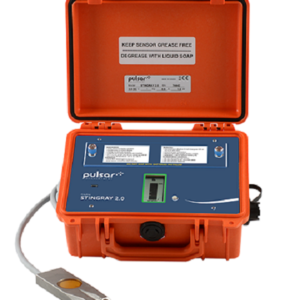
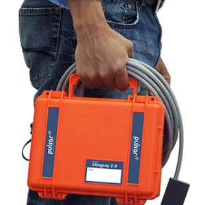
Stingray 2.0 Portable Level-Velocity Logger
- Measures water level and velocity in partially filled pipes and open channels
- No flume or weir required
- Extreme low power consumption Uses standard Alkaline D-cell batteries
- 130,000 point data logger
- USB output
- Powerful Windows software
- LCD bar graph display
-
 Request a QuoteQuick View
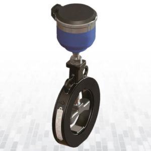
Mechanical Flow Meter Wafer Serie
Direct reading Flow Rate Indication
Optional (field adjustable) switch(es)
Optional Non-Contact 4-20mA Output
High Pressure available
Mounts in any orientation
No straight Pipe Run required • Connection sizes from 3” to 12” -
 Request a QuoteQuick View
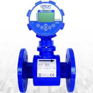
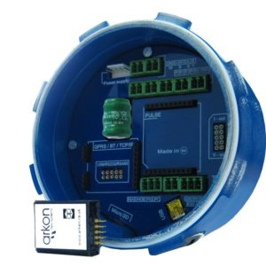
Electromagnetic Flow Meter MAGX2
MAGX2 offers a wide range of modules to allow each customer to “design” their own solution for his application. The modules are “plug and play”, can be easily installed or removed from the mother board (always check first that the unit is powered off) and have in most of the cases the size of a big post stamp.
Arkon modules are divided in:
- Power supply modules.
- Output modules.
- Digital communication modules.
-
 Request a QuoteQuick View
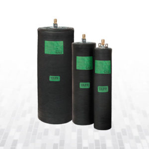
High Pressure Pipe Stoppers UU
If the standard sealing pipe stoppers cannot be used due to high back pressure, these high-pressure pipe stoppers are recommendable.
-
 Request a QuoteQuick View
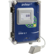
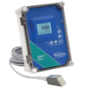
Doppler Ultrasonic Flowmeter DFM 5.1
- User-Friendly Calibration
- Password Protected
- Isolated 4-20mA Output
- 2 Control Relays
- Digital Signal Processing
- Optional Intrinsic Safety
